● Practical Guide
How to Increase Soil Stability: A Step-by-Step Field Guide
Increasing soil stability is not a single action — it is a structured process that begins with understanding what you have in the ground, selecting the right treatment for that specific soil and load condition, executing the treatment correctly, and verifying the result before building on it. This guide walks through the complete process: from site investigation to quality control, covering the decisions that determine whether a stabilization project succeeds or fails.
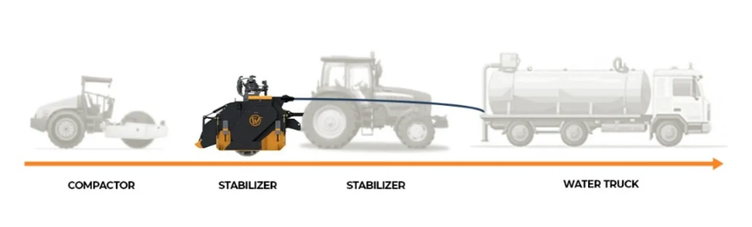
Step 1: Investigate the Existing Soil
No soil stability improvement programme should begin without understanding the existing ground conditions. Treating the wrong problem with the wrong method wastes money and produces an unreliable result. Site investigation answers three critical questions: what type of soil is present, how weak is it, and what is causing the weakness?
Field Testing
Field testing gives a rapid picture of soil strength variability across a site without laboratory delays. The most useful field tests for subgrade assessment are:
- Dynamic Cone Penetrometer (DCP) — A steel cone is driven into the ground by a standard drop weight. The number of blows per 100 mm of penetration (DCPI) is directly correlated to CBR. A DCPI above 30–40 mm/blow indicates a CBR below 3% — subgrade that requires stabilization before any pavement is placed.
- Plate Load Test — A steel plate is loaded incrementally on the prepared subgrade surface and settlement recorded. Gives the modulus of subgrade reaction (k), useful for rigid pavement design and for detecting soft spots that DCP might miss.
- Nuclear Density Gauge — Measures in-situ density and moisture content instantaneously. Useful for checking whether poor performance is due to under-compaction (fixable by re-rolling) or inherently weak soil (requires stabilization).
- Visual and tactile assessment — Experienced field engineers use simple indicators: the “boot test” (does your boot sink more than 25 mm?), the “shear vane” for clay strength, and visual inspection for cracking, rutting, and surface moisture. These are not substitutes for testing but identify where to focus investigation effort.
Laboratory Testing
Representative samples collected from trial pits or boreholes across the site are sent to a geotechnical laboratory for the following tests as a minimum:
- Particle size distribution (grading) — Determines the proportions of gravel, sand, silt, and clay. Identifies soil classification and guides binder selection.
- Atterberg limits (LL, PL, PI) — Identifies plasticity index. PI above 25 indicates a soil that needs lime treatment; PI below 20 is suitable for direct cement stabilization.
- Organic content — Organic material above 2% inhibits cement hydration. Soil with high organic content may need removal or specialist treatment.
- Sulphate content — Soluble sulphates above 0.5% prevent effective cement stabilization by forming expansive ettringite. Must be tested before specifying cement.
- Soaked CBR — The standard measure of subgrade bearing capacity for flexible pavement design. CBR below 5% typically triggers stabilization; CBR below 2% requires significant treatment.
Field Rule of Thumb
If your boot sinks more than 25 mm into the subgrade, or a DCP reading exceeds 30 mm/blow, the soil is unlikely to achieve even a CBR of 3% — well below the minimum for most road designs. Chemical stabilization is almost certainly required before pavement construction.
Step 2: Select the Right Method for Your Soil
The investigation results drive the method selection. There is no universal treatment — the right approach depends on soil type, severity of weakness, project requirements, budget, and timeline. The decision framework below covers the most common site conditions:
| Site Condition | Recommended Method | Key Constraint |
|---|---|---|
| Granular soil, low CBR, dry | Cement stabilization 3–7% | Compact within 2 hours of mixing |
| Sandy soil, erosion-prone | Cement stabilization 5–9% | Ensure adequate moisture for hydration |
| Low-PI clay (PI < 20), wet | Lime modification then cement | Allow 24–48 hr mellowing after lime |
| High-PI clay / Black Cotton Soil | Lime stabilization 3–6% (IRC:SP:89) | PI must reduce below 20 before overbuilding |
| Failed asphalt / granular road base | Full-depth reclamation with cement | Check for fuel/oil contamination first |
| Slope / embankment surface erosion | Vegetation + surface binder or geotextile | Establish cover before monsoon season |
| Agricultural compaction / hardpan | Mechanical subsoiling or rotary milling | Work at optimum soil moisture, not wet |
Step 3: Complete a Laboratory Mix Design
Once the treatment method is selected, the exact binder content must be determined through laboratory mix design using the actual site soil. This step is non-negotiable for any engineered stabilization — applying cement or lime at an arbitrary rate wastes money and produces uncertain results.
The standard laboratory mix design process for cement or lime stabilization:
Prepare trial mixes at multiple binder contents
Typically 3%, 5%, 7%, and 9% by dry soil mass. Compact each at its optimum moisture content using the Modified Proctor method to replicate field compaction energy.
Cure specimens under controlled conditions
Cylindrical specimens are cured at 40°C for 7 days (IRC:SP:89 method for India) or at 20°C for 28 days (European standard EN 14227). The accelerated 40°C curing simulates long-term Indian field curing conditions.
Test UCS and select the design binder content
The design binder content is the lowest content that achieves the target UCS. Using a higher content than necessary wastes binder cost and increases shrinkage cracking risk. A swell test is also performed on lime-treated specimens to verify that heave does not occur.
Calculate field application rate
Convert the design binder content (%) to a surface application rate (kg/m²) using the formula: Application Rate = (Binder % ÷ 100) × Treatment Depth (m) × Maximum Dry Density (kg/m³). This figure is what the binder spreader operator sets on the machine.
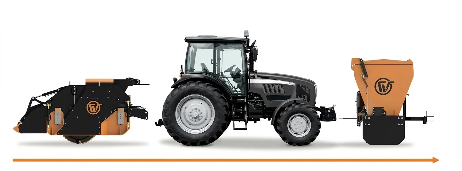
Step 4: Execute the Stabilization Works
Field execution is where most stabilization projects either succeed or fail. The laboratory mix design defines what needs to happen — the field team must execute it accurately and within the time constraints that the chemistry imposes. The following points are the most critical for a successful outcome:
Control Moisture Before You Start
The field moisture content of the soil at the time of treatment should be checked and, if necessary, adjusted before binder is applied. Soil that is significantly above optimum moisture content should be scarified and allowed to dry, or pre-treated with a small lime addition to reduce moisture. Soil that is too dry should be lightly pre-wetted. The goal is to reach OMC ±2% before binder spreading begins.
Spread Binder Accurately
Use a purpose-built binder spreader set to the design application rate. Verify the calibration by spreading over a known area, collecting the binder, and weighing it before the main works begin. Overlap at lane joints must be controlled to avoid double application. Binder that blows off the surface in wind must be accounted for — avoid spreading in wind speeds above 15 km/h when using dry powder binders.
Mix Uniformly with the Stabilizer Machine
这 soil stabilizer machine is set to the design treatment depth and makes its pass at a controlled forward speed — typically 3–6 m/min for cohesive soils, slightly faster for granular soils. Two passes at right angles improve mixing uniformity for difficult soils. Water addition during mixing brings the mix to OMC. Check that the full depth is being achieved by stopping and probing the mixed material — unmixed soil at the bottom of the treatment zone means the depth setting needs adjustment.
Compact Within the Working Time Window
For cement-stabilized soils, the entire sequence from binder spreading to completion of compaction must be finished within two hours in tropical conditions. This is the hardest constraint to manage in hot Indian summers, where temperatures above 35°C accelerate cement hydration and shorten the working window. Plan your production rate, equipment fleet, and water supply to ensure this window is consistently met. For lime stabilization, the working window is longer (4–24 hours), giving more operational flexibility.
“
In hot Indian conditions above 35°C, cement stabilization must go from spreading to compaction within two hours. Missing this window means starting again — at full material cost.
Step 5: Verify the Result with Quality Control Testing
Stabilization cannot be assumed to have worked just because it was executed according to plan. The quality of the result must be verified through systematic testing before the overlying layers are placed. Remediation of a failed stabilized layer after the pavement is built on top of it is far more expensive than catching the failure before construction continues.
| Test | When | Acceptance Criterion |
|---|---|---|
| Nuclear / Sand Replacement Density | During and after compaction | ≥97% of MDD from Modified Proctor test |
| Field Moisture Content | At time of compaction | OMC ±1.5% (IRC:SP:89) |
| UCS on Field Cores | 7 or 28 days after compaction | ≥design UCS (typically 1.5 MPa at 7 days) |
| DCP through stabilized layer | 7 days after compaction | Consistent refusal or low DCPI throughout treated depth |
| Atterberg Limits (lime treatment) | After mellowing, before overbuilding | PI reduced to design target (typically <20) |
Common Mistakes That Reduce Soil Stability Improvement
Soil stabilization failures in the field are almost always caused by process errors rather than by fundamental problems with the method itself. The most common mistakes to avoid:
- Skipping the laboratory mix design — Applying a “standard” cement rate without testing the specific site soil. Soil variability means there is no universal application rate. A mix design costs a fraction of the cost of a failed project.
- Compacting late — Allowing more than two hours to elapse between cement mixing and final compaction. Partially hydrated cement produces a weak, laminated layer that fails rapidly under traffic.
- Under-compacting — Failing to achieve the specified density because the roller is too light, makes too few passes, or the moisture is too far from OMC. Under-compacted cement-stabilized soil has high void space, poor binder-particle contact, and low UCS.
- Poor curing — Leaving the compacted surface exposed to sun and wind without a curing membrane or moisture cover. The top 20–30 mm desiccates and crumbles, and the underlying layer is weakened. Apply a curing membrane or cover within 30 minutes of completing compaction.
- Using cement on high-PI clay without lime pre-treatment — Cement does not effectively mix into or chemically react with high-plasticity clay. The result is a non-uniform material with pockets of sticky, unmixed clay. Always reduce PI below 20 with lime before applying cement to expansive soils.
- Opening to traffic too early — Allowing heavy vehicles onto a cement-stabilized layer before it has developed sufficient strength (minimum 7 days, ideally 14 days before surfacing). Early loading before the cement matrix has formed permanently damages the layer.
Frequently Asked Questions
QHow quickly can soil stability be improved?
Lime modification of wet clay gives immediate workability improvement within hours of mixing. Cement stabilization achieves meaningful structural strength within 7 days. A typical rural road subgrade — 2–3 km of lane — can be fully stabilized and ready for surfacing within 2–3 weeks from start of works, depending on equipment and crew size.
QCan soil stability be increased without chemicals?
Yes, through mechanical compaction, drainage improvement, and geosynthetic reinforcement. These methods are effective for granular soils and for situations where the primary problem is under-compaction or high moisture content. However, for cohesive clays with high plasticity — the most common problem soil in India — chemical treatment is almost always required to achieve a lasting improvement in stability.
QHow do I know if my soil needs stabilization or just better compaction?
Test the density first. If the in-situ density is below 90% of MDD, compaction alone may be sufficient. If density is already near MDD but the soil still fails under load or fails the CBR test, the problem is inherent in the soil properties — too much clay, too much moisture sensitivity, too low bearing capacity — and chemical stabilization is required. A DCP test before and after re-rolling will confirm whether additional compaction is delivering any benefit.
QWhat is the minimum CBR required for a road subgrade in India?
Under IRC:37 (Guidelines for the Design of Flexible Pavements), the design CBR of the subgrade determines the structural number and pavement thickness. A soaked CBR of 5–8% is typical for moderately trafficked rural roads; heavily trafficked national highways may specify a minimum of 10% CBR at the top of the subgrade. Subgrade below these values requires stabilization before the pavement is designed.
QDoes increasing soil stability also reduce erosion?
Yes, significantly. Chemical stabilization binds soil particles together, dramatically increasing resistance to erosion by water flow and wind. A cement-stabilized or lime-stabilized surface resists the scouring forces of monsoon runoff that would strip several centimetres of loose topsoil in a single heavy rainfall event. This is why stabilization is also used for embankment slopes, canal banks, and agricultural field margins in erosion-prone areas.
Key Takeaways
- Increasing soil stability always starts with investigation — soil type, CBR, PI, organic content, and sulphate content all determine the correct treatment
- A laboratory mix design is non-negotiable — there is no universal binder rate for all soils
- Cement stabilization must go from spreading to compaction within 2 hours — the hardest constraint in hot Indian conditions
- High-PI clays must be lime pre-treated before cement is applied — cement alone does not work on Black Cotton Soil
- Quality control testing — density, moisture, UCS cores — must confirm the result before overlying layers are placed
- Most stabilization failures are process errors — late compaction, poor curing, wrong binder — not fundamental method failures
Increasing soil stability is a proven, achievable, and cost-effective objective on any construction or land improvement project — provided the correct process is followed from site investigation through to quality control. The THOR ST Soil Stabilizer from India Watanabe Soil Stabilizer Co.,Ltd is designed to execute the critical mixing step with the depth control, uniformity, and reliability that a successful stabilization project demands. Contact our team to discuss your site conditions and project requirements.